

If you’re wondering “how to drawn an Arrow in AUTOCAD?” this blog is worth a read.
Learning to draw arrows in AutoCAD can be extremely useful, especially when creating technical drawings, architectural plans, or diagrams.
Here’re 5 methods that work best for drawing arrows:
- LEADER command (MLINE) – Just type in the leader command in the command bar and follow the prompts. (This command works for most computers and version of AutoCAD).
- Using TOOL PALETTE – Now if you don’t want to use a command, you can use the arrow tool from the TOOL PALETTE.
- Using POLYLIN – That’s the most common of all methods. You won’t need any special command; instead you use the thickness of polyline and taper it to form an arrow shape. (This method works best to draw an arrow on Mac and Window users).
- QLEADER or MLEADER – So, this method works only for Mac users; just type in the command and select to start the arrow line.
- ARROW command – It only works if you have got the CARLSON Plugin in your AUTOCAD. Just type in the command and select which side of the line you want to arrow to appear.
Now in our today’s blog, I’ll try to explain all of these methods one by one.
MLINE Command Method
Let’s see how to create a line with an arrow.
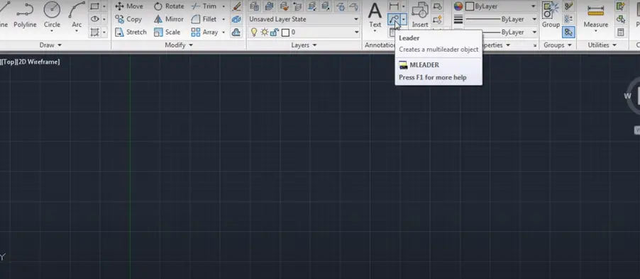
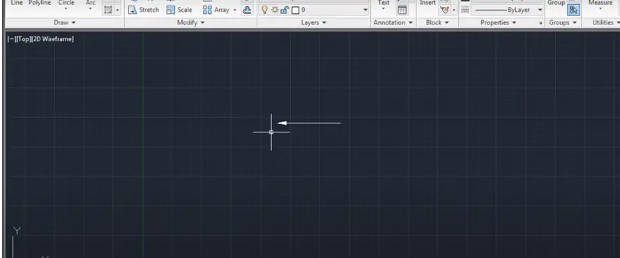
So, for creating a line with an arrow, we will use the multileader (MLINE) command.
- Here, click on “Leader,” then specify the first point.
- Suppose I want a straight line, so give this second point and press “Escape.”
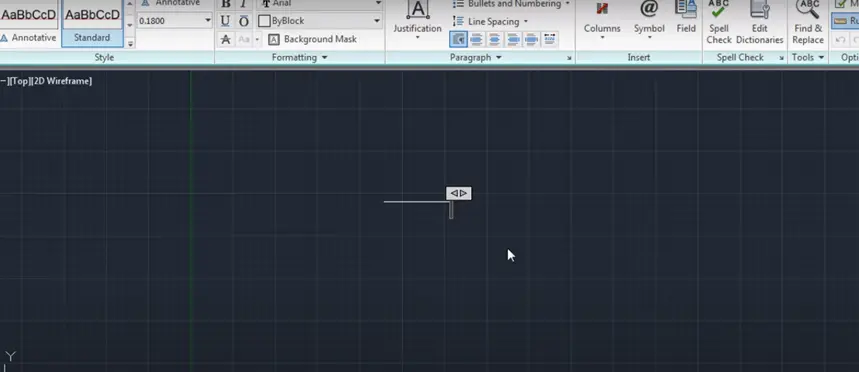
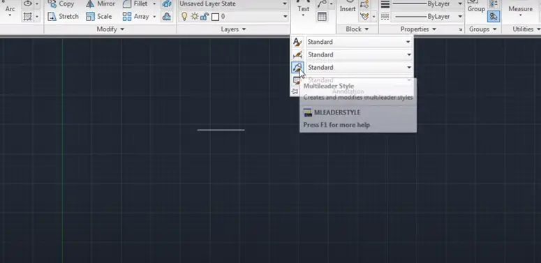
- Now, the arrow is not visible. For that, you need to go to “Annotation” and click on “Multileader Style” to modify it. Click on “Leader Structure” and specify the scale to increase it, then click “OK” and close the dialog box.
- Now, the arrow is visible.
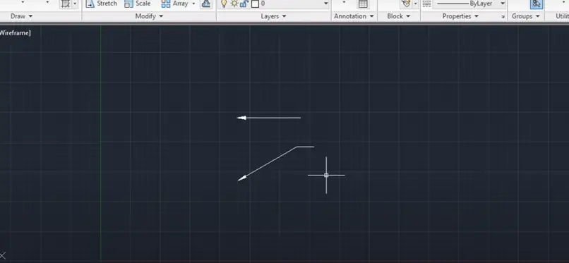
- You can also create an inclined line.
- Just click on “Leader,” give the first point, give the second point, and press “Escape.”
- Suppose if you don’t want this extra line, you’ll have to explode it. Just click on “Xplode” (X) and click on the line. Then press “Enter,” and the extra line will be removed.
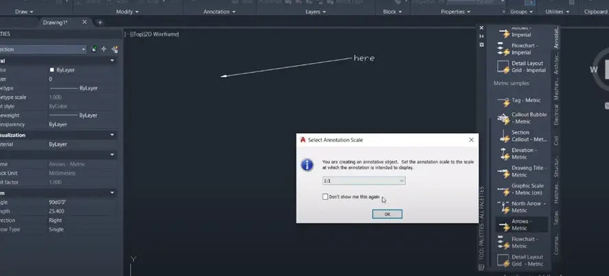
- In this way, you can create a straight line with arrows. If you want to add text, that’s also possible. Using the “Leader” command, give the first point, then the second point, and add the text. Suppose I want to write “here.” Click outside to place the text.

- Also, you can create lines with ticks. After that, you can add text by simply using the “Leader” command and giving the first and second points.
- To create an inclined line with text, go to the first point, then the second point, and write what you want to write. Close the text editor when you’re done.
- In this way, you can create lines with arrows, without text, with text, and inclined lines too.
Also Read: How to make dotted line in AutoCAD? (Easiest way)
Tool Palette Method
First, you need to open up the tool palette. To do this, you can just start typing ” TOOLPALETTE “and hit “Enter.”

Then, under the “Annotation” tab, you can scroll down to find “Arrows.”

There are options for “Arrows Imperial” or “Arrows Metric.”
For this instance, I’ll select “Metric.”
You can click where you want the arrow to be placed.
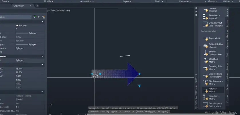
There’s a whole bunch of dynamic features with this tool. You can use it to set the length of the arrow, adjust the rotation of the arrow, and change the arrow type. It can be a double arrow, single arrow, or even a fancy arrow.
Additionally, you can change the direction of the arrow just by clicking the end of that node.
Also Read: AutoCAD vs AutoCAD Architecture 2022: Everything You Must Know
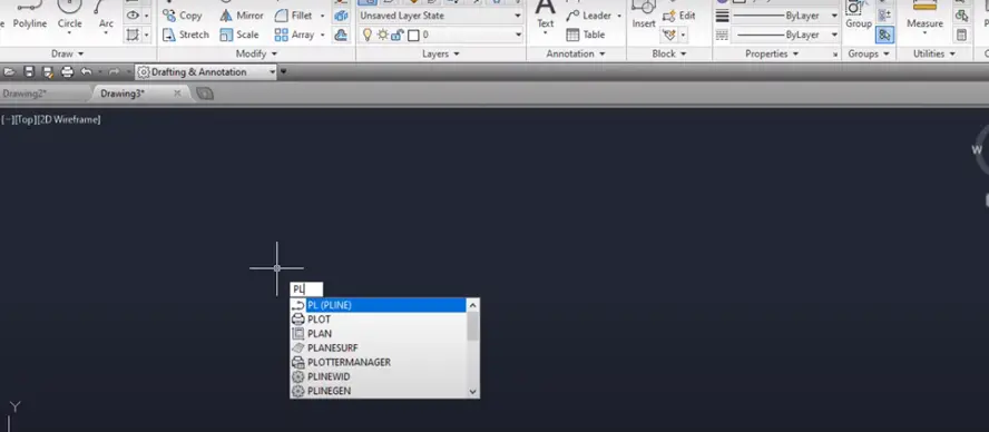
Polyline Method
Type the word “POLYLINE“ into the command bar to open the polyline Method.
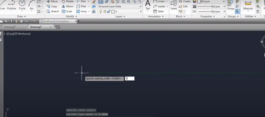
Select the model space by clicking the left hand of mouse then press W to open the width option, then enter zero (start of arrow head).
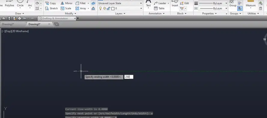
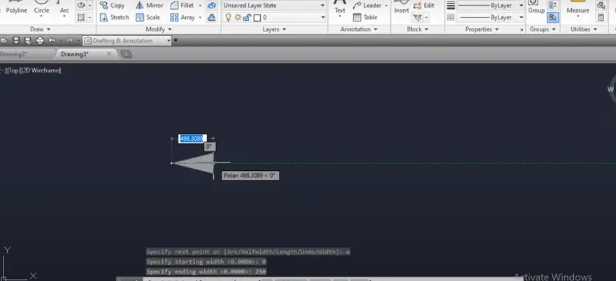
By clicking left of the mouse, again select the second point which is end of arrow, then press W command again to change the width to five or some what that is acceptable.
Curved arrow can be drawn by using this method in AutoCAD.
Tips for Precision Drawing
Drawing arrows with precision is essential, especially in technical drawings. Here are some tips to ensure accuracy:
Snapping Tools: Utilize AutoCAD’s snapping tools to align your arrow precisely. Snapping options like Endpoint, Midpoint, and Intersection can be extremely helpful.
Object Tracking: The Object Snap Tracking feature helps you draw arrows parallel or perpendicular to existing objects, maintaining consistency in your design.
Ortho Mode: Activate Ortho mode by pressing the F8 key. This feature restricts cursor movement to horizontal and vertical directions, ensuring straight arrows.
Polar Tracking: Polar tracking allows you to draw arrows at specific angles, facilitating more accurate drawings.
Given below are five methods which can be used as per your convenience to draw lone in AutoCAD.