Saad Iqbal | 🗓️Modified: September 29, 2016 | ⏳Read Time: 11 min | 👁Post Views: 2103
The word asphalt, asphaltic concrete, bituminous mixes all is pointing to the same things almost. The shining blackish paved road we ride almost every day and almost several hours of our lives are spent over them is asphaltic pavements.
 |
| You know asphalt pavements have the highest riding quality among all others |
The transportation engineers, know that the two basic types of pavements is rigid pavement or flexible pavement. Flexible pavement deforms slightly under the application of the dynamic load of traffic whereas rigid pavement is the one that stands firm and it bridges the voids and gaps in the underneath bearing soil.
We would not here go into the details of these but as far as flexible pavements are concerned these are one of the most common, high riding quality paved roads on earth. The flexible pavements have a wearing course (the top few cms of the highway which is expected to get wear and tear due to traffic movement) which is made up of high quality fine asphaltic concrete.
Asphalt is basically combination of bitumen and aggregate, the surface of aggregates are applied with bitumen and then bitumen acts as a binding agent that makes it a solid and firm material called asphaltic concrete.
Like we all know about traditional Portland cement concrete that its properties and strength is largely dependent on the amount and proportion in which the constituents are mixed, same is the case here in asphaltic concrete.
What is HMA or Hot Mix Asphalt
Sometimes there is a term written in some texts as HMA or Hot Mix Aspahlt it is basically the same thing like that of Bitumen as asphalt binder and aggregate.
HMA mix design is the process of determining what aggregate to use, what asphalt binder to use and what the optimum combination of these two ingredients should be.
Main objective is to determine an economical and workable mix which comprises of a suitable blend of aggregates and a corresponding asphalt content.
What is Job Mix Formula (JMF)
The end result of a successful mix design is a recommended mixture of aggregate and asphalt binder. This recommended mixture, which also includes aggregate gradation and asphalt binder type is often referred to as the job mix formula (JMF)
Properties of Ideal Asphaltic Concrete Mix
The main objective of the Job Mix Formula, Mix Design Method, Marshall Mix Design method is to determine an ideal and optimum asphalt mix that has following properties :-
1. Resistance to permanent deformation: The mix should not distort or be displaced when subjected to traffic loads. The resistance to permanent deformation is more important at high temperatures.
2. Fatigue resistance: the mix should not crack when subjected to repeated loads over a period of time.
3. Resistance to low temperature cracking. This mix property is important in cold regions.
4. Durability: the mix should contain sufficient asphalt cement to ensure an adequate film thickness around the aggregate particles. The compacted mix should not have very high air voids, which accelerates the aging process.
5. Resistance to moisture-induced damage.
6. Skid resistance.
7. Workability: the mix must be capable of being placed and compacted with reasonable effort.
8. Low noise and good drainage properties: If the mix is to be used for the surface (wearing) layer of the pavement structure.
Marshall Method of Mix Design
According to ASTM D1559 which uses Marshall mix design method for getting JMF as optimum Aspahlt Mix, there are 6 basic steps involved in it :-
- Aggregate Selection
- Asphalt Binder Selection
- Sample Preparation (including compaction)
- Density and voids calculations
- Stability determination using the Marshall Stability and Flow test
- Optimum asphalt binder content selection
There are two major features of the Marshall method of designing mixes namely,
- density – voids analysis
- Stability – flow tests.
Marshall Mix Design Procedure
The first step in the Marshall Mix Design method is to prepare the samples as described below :-
The aggregate gradation is selected from the following table and then after sieving the desired quantity of each gradation approximately 1200 grams of aggregates are taken.
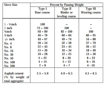 |
| Table no. 1 Aggregate Specification |
The aggregates are then heated to a temperature of 175 to 190 degree centigrade. As for first trial 3.5 to 4.0 percent by weight of the aggregates Bitumen is taken and heated to a temperature of 121 to 125 degree centigrade.
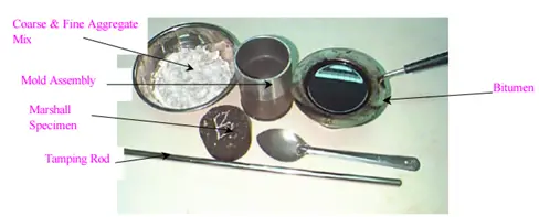 |
| Sample Preparation |
The Marshall Mold Assembly is preheated and the heated aggregates and bitumen are thoroughly mixed at temperature of 154 to 160 degree centigrade and then placed in the mould.
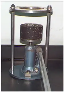
The mould is then compacted by Marshall Hammer device with 50 blows on each side of the mixture at temperature around 138 to 149 degree centigrade.
 |
| Marshall Drop Hammer |
In the next trial the Bitumen content is varied by +0.5 % of the weight of mineral aggregate and above procedure is repeated to have a required number of specimen to be tested.
After the preparation of the sample, the properties of the mix is determined. The properties that are of interest include
1. Theoretical Specific Gravity (Gt)
2. Bulk Specific Gravity (Gm)
3. Percent Air Void (Vv)
4. Percent Volume of Bitumen (Vb)
5. Percent Void in Mixed Aggregate (VMA)
6. Percent Voids Filled with Bitumen (VFB)
Theoretical Specific Gravity
Specific gravity or relative density is the weight of the substance compared with the weight of a standard reference object, usually water, at equal volume and at some specified temperature. It actually gives us the idea that how much one object is heavier than the reference object or water.
Theoretical specific gravity Gt is the specific gravity without considering air voids that means it is the specific gravity of the sample when zero air voids exists and maximum compaction is achieved. The maximum specific gravity of the aggregate admixture should be obtained as per ASTM D2041, however the difficult procedure mostly following equation is used to calculate the maximum specific gravity.
Bulk Specific Gravity
Bulk specific gravity is the actual specific gravity Gm while considering air voids and it is found by the following formula :-
Where Wd is the Dry weight of the sample, WSSD is the Saturated Surface Dry Weight and Wsub is the weight of the sample in water.
To get accurate bulk specific gravity, the specimen is coated with thin film of paraffin wax, when weight is taken in water. This however requires to consider the weight and volume of wax in the calculation.
Air Voids Percent Vv
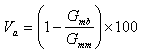
Air voids Vv is the percent of air voids by volume in the specimen. The total volume of the small interstices or voids of air between the coated aggregate particles throughout a compacted paving mixture, expressed as a percent of the bulk volume of the compacted paving mixture. It is expressed as :-
Where Va or Vv is the air voids percentage
Gmb = Bulk specific gravity of compacted asphalt mixture.
Gmm = Theoretical maximum specific gravity of Bituminous Paving Mixtures
Percent Volume of Bitumen Vb
It is the percent volume of bitumen in the total volume of the mix.
Voids in Mineral Aggregate (VMA)
The percent voids in Mineral Aggregate (VMA) is the percentage of void spaces between the granular particles in the compacted paving mixture, including the air voids and the volume occupied by the effective asphalt content.
VMA = 100 – (Gbcm x Pta)/ Gbam
Where
VMA = percent voids in Mineral Aggregates
Gbcm = bulk specific gravity of compacted specimen
Gbam = Bulk specific gravity of aggregate mixture
Pta = aggregate percent by weight of total paving mixture.
Voids Filled with Bitumen VFB or Voids Filled with Aspahlt (VFA)
Voids filled with bitumen is the voids in the mineral aggregate framework filed with the bitumen.
The portion of the voids in the mineral aggregate that contains asphalt binder.
VFA = VMA – Pa
Where
VMA = percent voids in Mineral Aggregates
Pa = Percent air voids
After the preparation of the sample and determination of the properties mentioned above the Sample is taken for the Marshall Stability and Flow test.
Marshal Stability and Flow Test
After the sample preparation, the sample is extracted with the help of sample extractor as show :-
 |
| Marshall Sample Extractor |
The extracted sample is immersed in a bath of water at a temperature of 60 degree centigrade for a duration of 30 minutes. The sample is then placed in a
Marshall Stability Testing Machine and loaded at a constant rate of deformation of 5 mm per minute until failure. The Total Maximum load in kN that causes the failure of the specimen is taken as Marshall Stability. The stability value is also corrected for volume it will be explained later.
The Flow Value is also determined as :-
The total amount of deformation in units of 0.25 mm that occurs at maximum load is called flow value.
The total time between removing the specimen from the bath and completion of the test should not exceed 30 seconds.
The marshall stability and test provides the performance prediction measures for the Marshall Mix Design Method.
Marshall Stability and flow values along with density, air voids in the total mix, voids in mineral aggregates or voids filled with asphalt or both filled with asphalt are used for laboratory mix design and evaluation of asphalt mixtures. In addition, Marshall Stability and flow can be used to monitor the plant process of producing asphalt mixtures. Marshall Stability and flow may also be used to relatively evaluate different mixes and the effect of conditioning such as with water.
The Marshall Stability and flow test results are applicable to dense-graded asphalt mixtures with maximum size aggregate upto 1 in. in size. For the purpose of mix design, Marshall Stability and flow test results should consist of the average of a minimum of three specimens at each increment of binder content range is generally selected on the basis of experience and historical testing data of the component materials, but may involve trial and error to include the desirable range of mix properties.
Stability, flow, density, air voids, and voids filled with asphalt binder, may be plotted against binder content to allow selection of an optimum binder content for the mixture.
Selection of Optimum Asphalt Binder Content
The optimum asphalt or Binder content is actually determined after analyzing the results obtained from Marshall stability and flow test, density analysis, voids analysis.
The procedure to determine optimum Binder content is as under :-
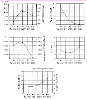
1. Plot the following graphs and charts
a. Between Asphalt Binder content (x – axis) and % air voids (y-axis) – usually with increase in binding content the percent air voids decreases.
b. Between Asphalt Binder Content (x – axis) and Density (y-axis) – usually with increase in asphalt content the density increase but after a peak it lowers down.
c. Between Asphalt Binder content (x-axis) and Flow (y-axis) – usually it exhibits a liner or near to linear relation.
d. Between Asphalt Binder Content (x-axis) and Marshall Stability (y-axis) usually it show a parabolic like curve with linear relation at the start and after a peak it goes down
e. Between Asphalt Binder Content (x-axis) and VFA % (Voids Filled with Asphalt or Binding Agent) it also usually shows a near to liner relation
f. Between Asphalt Binder Content (x-axis) and %VMA (Voids in Mineral Aggregate) (y-axis) it shows reverse parabola with reveres relation at start and then linear relation at the end.
2. With the help of the graphs plotted Three bitumen content are noted :-
a. Binder content corresponding to maximum stability
b. Binder content corresponding to maximum bulk specific gravity
c. Binder content corresponding to median of designed limits of percent air voids (Vv) usually 4%. The stability value, flow value and VFA are checked with Marshall Mix Design Specification chart and the optimum Binder content is determined.
Sometimes the Optimum Binder content is also taken as the average of the Binder content corresponding to maximum unit weight, maximum stability and at specific (i.e. 4 %) air voids.
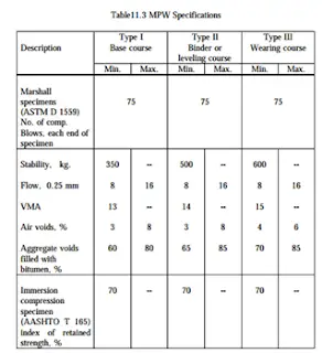
The results should always be in the range as shown :-