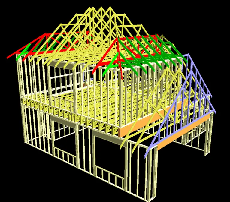
 |
| Finite Element Analysis |
Definition of Finite Element Analysis
According to one definition;
Finite element method (FEM) is a technique for numerical solution of complex structural problems. In this method the structural system (consisting of all the elements which make up a structure) is modeled by a set of appropriate finite elements which are interconnected at points called nodes. Elements may have physical properties such as thickness, coefficient of thermal expansion, density, compressive strength, yield strength, young’s modulus, shear modulus and Poisson’s ratio.
Use of FEM
Traditionally, engineers have used laboratory testing to investigate the structural behavior of steel building products and systems subject to the expected wind and earthquake loads and to develop appropriate design rules. Laboratory testing was also used to develop new building products and systems. However, such reliance on time consuming and expensive laboratory testing has hindered progress in this area. The product manufacturers and designers often decided on conservative designs in order to avoid expensive and time consuming laboratory testing. However, advances in the field of computer aided engineering during the last two decades have changed this situation significantly in many engineering industries.
The finite element method (FEM) is the dominant discretization technique in structural mechanics. The basic concept in the physical interpretation of the FEM is the subdivision of the mathematical model into disjoint (non-overlapping) components of simple geometry called finite elements or elements for short. The response of each element is expressed in terms of a finite number of degrees of freedom characterized as the value of an unknown function, or functions, at a set of nodal points.
The response of the mathematical model is then considered to be approximated by that of the discrete model obtained by connecting or assembling the collection of all elements. The disconnection-assembly concept occurs naturally when examining many artificial and natural systems. For example, it is easy to visualize an engine, bridge, building, airplane, or skeleton as fabricated from simpler components. Unlike finite difference models, finite elements do not overlap in space.
A typical finite element analysis on a software system requires the following information:
1. Nodal point spatial locations (geometry)
2. Elements connecting the nodal points
3. Mass properties
4. Boundary conditions or restraints
5. Loading or forcing function details
6. Analysis options
Because FEM is a discretization method, the number of degrees of freedom of a FEM model is necessarily finite. They are collected in a column vector called u. This vector is generally called the DOF vector or state vector. The term nodal displacement vector for u is reserved to mechanical applications.
FEM Solution Process
Procedure
1. Divide structure into pieces (elements with nodes) (discretization/meshing)
2. Connect (assemble) the elements at the nodes to form an approximate system of equations for the whole structure (forming element matrices)
3. Solve the system of equations involving unknown quantities at the nodes (e.g., displacements)
4. Calculate desired quantities (e.g., strains and stresses) at selected elements
Like Us on Facebook!
Basic Theory
The way finite element analysis obtains the temperatures, stresses, flows, or other desired unknown parameters in the finite element model are by minimizing energy functional. Energy functional consists of all the energies associated with the particular finite element model. Based on the law of conservation of energy, the finite element energy functional must equal zero. The finite element method obtains the correct solution for any finite element model by minimizing the energy functional. The minimum of the functional is found by setting the derivative of the functional with respect to the unknown grid point potential for zero. This is based on the principle of virtual work, which states that if a particle is under equilibrium, under a set of a system of forces, then for any displacement, the virtual work is zero. Each finite element will have its own unique energy functional.


