 |
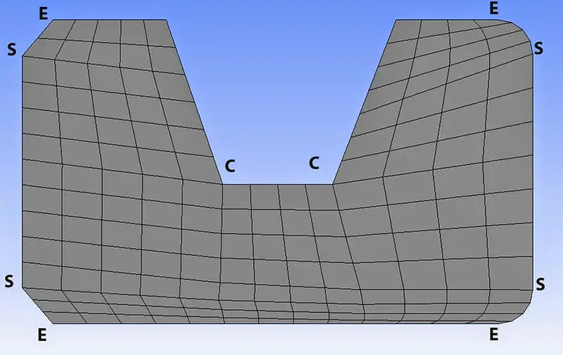
| Meshing of an element |
Use of Meshing
In the past decade there have been many important theoretical advances in algorithm design for meshing related problems, but only some of these have made it into meshing software.
Lateral walls and semi-rigid diaphragms are composed of shell elements. The subdivision of these elements into smaller pieces is commonly referred to as meshing.
In Ram Frame, the size of the mesh is controlled by the “Maximum distance between nodes” parameter in Ram Frame – Criteria – General. When a lateral beam has an internal node at a column or brace end, the beam is segmented in the finite element model and the beam is represented by two beam segments. These finite element segments are denoted by the use of I’ and j’ in the results. The first segment ends are I and j’ and the second segment ends are I’ and j. Therefore, I’ and j’ are always the ends at the internal node.
Meshing types
Coarse: Faster computation; not concerned about stress concentrations, singularities, or warping. Not near changes in geometry or displacement constraints or changes in material including thickness.
Fine: Best approximation but at the cost of the computation time. Look for disproportionate stress level changes from node to node or plate to plate and large adjacent node displacement differences to determine if need to refine the mesh. Nodes should be defined at locations where changes of geometry or loading occur. Changes in geometry relate to thickness, material and/or curvature. A simple check, if you can, is to decrease the mesh size by 50%, re-run analysis, and compare the change of magnitude of stresses and strains. If there is no significant change, then ok. In most companies, all of this knowledge of mesh size will be known and might
be set a FEA control file.
In case of the slab supported on beams we know in actual conditions the beam is monolithic with the slab that means that beam acts as a T-Beam with the slab having flange the portion of the slab. But during modeling in finite element analysis the slab or area or shell element is acted separately and the beam is acted separately. To make them monolithic we do the meshing of the shell element and divide the panels in to various sub-panels or parts which would then be attached to the beam from all the separated segments.