
So from above we can conclude that the building was designed and meant to accommodate humans, but as human brain has built-in functions to save the life and avoid death / injury as much as possible, therefore this building does not serve its purpose as it is scary and have a chilling effect in it. After said that we can now understand the actual meaning of serviceability of a building, in general and of a concrete structure, in particular.
Similarly bending in beams or buckling in columns is also a serviceability criterion that must be kept minimum or within the required ranges as per the code generally used within the locality.
As a student of Structural engineering you might already know about two different methodologies for designing a structure generally. Let me remind you in short, these two methods are named as :-
1) Allowable Stress Design Method
2) Ultimate Strength Design Method
In Allowable Stress Design procedure, for any particular type of material used for structure; like timber, concrete, steel an allowable stress range is decided and provided by the code. The designer is bound to keep the internal as well as external stresses within those limits. Concrete Structures in Allowable Stress Design procedure is never allowed to have even small cracking on its surface.
But the above method of design has some limitations; a Major one of those is larger cross-sections and excessive reinforcement. But this was adopted in the past as the knowledge about different materials of construction was limited as well as not that exact and trustful. However, with advancement in material engineering, the material engineer started believing in their knowledge and in the strength of the construction materials.
Ultimate strength design procedure utilizes the fullest of the available strength of materials i.e. allowing the steel to get yielded up to certain extent and even consider a minimum cracks of certain width not a safety hazard for the occupants.
So after the above discussion we can conclude :
1) A concrete structure is expected and is somehow healthy to be of a cracked section, but only within certain limits and ranges.
2) The crack within the concrete member needed to be within a limit so as to fulfill the serviceability criterion of the code.
One other reason to keep the crack within limit, beside serviceability, is sustainability is now explained. A Reinforced Cement Concrete Beam having a mesh of steel reinforcement cannot sustain its complete compressive as well as tensile strength if the moisture can get penetrated to the embedded steel rebars through the allowed cracks.
Due to that reason, the ductility, capacity, energy absoption, stiffness and structural performance of the concrete demands the designer to keep the width of the crack minimum and within a control.
The width of the crack can be assumed to depend on following :
1) Nature of the reinforcing steel
2) Spacing of the flexural steel reinforcement
3) Nature of bond between steel bar and that of tension zone of concrete.
Now let me explain to you that why actually we want the concrete to get crack a bit?
A general answer is actually already provided above, however, we can discuss that in detail here from strength of materials point of view. We know from strength of materials that concrete is strong in compression and weak in tension with tensile strength only a fraction of compressive strength of concrete.
If we consider a beam with modulus of rupture in such a range that at modulus of rupture the stress in concrete is around 500 psi, then the stress within steel according of modular ratio relation would be 500 x 8 (assuming a general value of modular ratio of 8) = 4500 psi or 4.5 ksi whereas the yield strength of the steel reinforcement is around 40 to 75 ksi ( It is important here to know that Grade of steel recorded in the drawings or in the specifications of a project is actually the yield strength of the steel reinforcement bars in thousands of Psi like Grade 60 steel would mean fy = 60,000 psi).
For those who don’t know Modular ratio for reinforcement and concrete is the ratio of modulus of elasticity of steel rebar with that of modulus of elasticity of Concrete i.e. n=Es / Ec.
As for beam considered above the stress in steel reinforcement is way below the yield strength of the steel rebar therefore providing reinforcement in the steel is of no use in such a case.
Now in the next coming paragraphs we will try to talk about the equations that is usually used to calculate the width of crack in a concrete member. Two common equations that have found applications in the ACI code are :-
1) Gergely and Lutz equation (z-factor method)
2) Frosh Equation
The above mentioned equations utilizes the conclusions and findings from series of tests and experiments.
Gergely and Lutz Equation
Gergely and Lutz used test results from Hognestad, Kaar and Mattock, Kaar and Hognestad, Clark and Rush and Rehm to conclude their equation for the calculation of crack widths at the tension surface.
The Original equation developed by Gergely and Lutz is as follows :-

Where Ws is the maximum crack width at level of steel reinforcement in mm
fs = the stress in the steel reinforcement in N/mm^2
Ao = Area of concrete surrounding each bar. This is measures by dividing total effective concrete tension area surrounding reinforcement having identical centroid by total number of bars (mm^2)
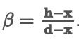
To obtain the maximum crack width(Wm) at extreme tensioned fiber the above equation is multiplied by a factor β.
Frosh Equation
According to Frosh , the maximum concrete cover, c used in the test analyzed by Gergely and Lutz was 84 mm and only three specimens of their test group among 612 observations had clear covers greater than 64 mm.

According to Frosh their equation is valid for a relatively narrow range of concrete covers (i.e. upto 63 mm). The use of thicker concrete covers is increasing because research and experience have indicated that the use of thicker covers can increase durability. Therefore, Frosh developed the following simple, theoretically-derived equation to predict crack widths that could be used regardless the actual concrete cover.
ACI Code Provision
According to ACI 318-95, the flexural crack control requirements must be in accordance with z-factor method developed by Gergely and Lutz. Following the extensive statistical analysis techniques on experimental data from several researchers. The equation used is as follows :-
The factors involved in the above equation to use the crack width is already explained above.